|
Material Properties Data Entry
|   |
|
Material Properties Data Entry
| |
All inputs that appear in this input section are required. User inputs are white, while calculated values are light blue.
Material Selection
Select material of construction from the dropdown list.
Min Specified Ambient Yield Strength Input
Select radio button indicating the source of minimum specified yield strength at ambient temperature: "Materials Table" or "User Specified".
Minimum Specified Yield Strength at Ambient Temperature
When "Material Table" is selected, the value is looked up in the Software's Materials Table using the selected Material of Construction. Note that the yield strengths tabulated values are at ambient condition and are taken from ASME BPVC II Part D. This value is only used in the Fracture Toughness calculation when using [1] Para F.4.4.
User Entered Min Specified Yield Strength at Ambient Temperature
When "User Specified" is selected, user will enter this value at Ambient Temperature in the requested units (psi or MPa). This value is only used in the Fracture Toughness calculation when using [1] Para F.4.4.
Min Specified Yield Strength at Assessment Temperature
User Entered Yield Strength at the Assessment Temperature. This is used in calculation of load ratio for the FAD assessment, KIC values per ASME Section VIII, Div. 3, and flow stress.
Fracture Toughness Option
Select from the dropdown control one of four approaches for determining the fracture toughness. References [1] and [2] can be consulted for the fracture toughness formulations. See the below notes in User Entered KIC and Charpy V-Notch for the case of Austentic Stainless Steel.
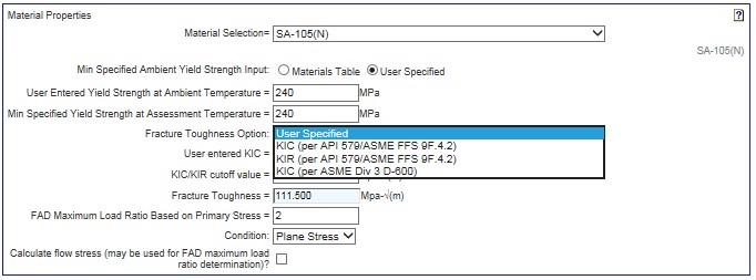
User Entered KIC
This input is required when "User Specified" is the selected Fracture Toughness Option. Enter in the requested units.
Reference [1], paragraph 9F.4.8.2 recommends for Austenitic Stainless Steels, to use 220 MPa sq. rt.(m) (200 ksi sq. rt.(in)) for base metal and 132 MPa sq. rt.(m) (120 ksi sq. rt.(in)) for weld metal.�
KIC/KIR cutoff value
Enter the cutoff value for the fracture toughness in the requested units. If the calculated value is higher than the cutoff value, the cutoff value is used.
Charpy V-Notch
For ASME Div 3 D-600 correlation, use the CVN values given in part KM of Reference [2]. The Charpy Conversion for austenitic stainless steel is not valid and should not be used.�
Fine Grained and Normalized?
Select appropriate radio button option. Required for [1] Part 9F.4.2 fracture toughness calculation.
Material Curve
The ASME material exemption curve is looked up in the Materials Table based on Material Selected and Fine Grained and Normalized status. Required for [1] Part 9F.4.2 fracture toughness calculation.
Assessment Temperature
Enter minimum component operating temperature in the units (F or C) requested. Required for [1] Part 9F.4.2 fracture toughness calculation.
Young's Modulus
This value is looked up in the Materials Table and is Young's Modulus at Ambient Temperature. This value is used in the [1] Part F.4.4 fracture toughness calculation.
KIC (per API 579 9F.4.2)
Calculated KIC value per [1] Para 9F.4.2. Only visible for this option.
For this option Cv is set to 15 ft-lbs (20 Joules), which is appropriate for Carbon Steel
KIR (per API 579 9F.4.2)
Calculated KIR value per [1] Para 9F.4.2. Only visible for this option.
For this option Cv is set to 15 ft-lbs (20 Joules), which is appropriate for Carbon Steel
KIC (per ASME Div 3 D-600)
Calculated KIC value per [2] Div 3 D-600. Only visible for this option.
Fracture Toughness
Value of fracture toughness used for the assessment, based on inputs and correlation selected.
FAD Maximum Load Ratio
This value is set at follows (see API-579, Figure 9.19)
|
C-Mn steels |
1.25 |
|
ASTM-508 |
1.15 |
|
Austenitic Stainless Steels |
1.8 |
|
If the flow stress (σf) and yield stress (σYS) are known |
σf/σYS |
|
If strain hardening characteristics are unknown, or there is a yield point plateau (strain hardening exponent > 15): |
1.0 |
Condition
Select Plane Stress or Plane Strain Case
Engineering Ultimate Tensile Stress at Assessment Temperature
Enter the Engineering Ultimate Tensile Stress at the Assessment Temperature in the requested units (psi or MPa). This is used for calculation of flow stress.
Max Allowable Stress at Assessment Temperature
Entered the Maximum Allowable Stress at Assessment Temperature in the requested units (psi or MPa). This is used for calculation of flow stress.
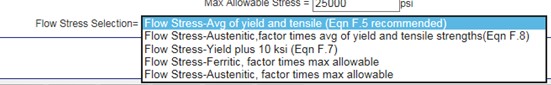
Flow Stress Selection
Select from the dropdown. The flow stress calculation can be used to set the FAD Maximum Load Ratio as shown above.