|
Components
|   |
|
Components
| |
On this page, an assembly of components is created, allowing the software to compute each connection's governing thickness and minimum allowable temperature (MAT) and report the limiting MAT for the assembly or vessel. Only components which control the vessel's MAT need be entered on this page.
An assembly consists of a number of components which are connected via weld or bolt. Where bolted or welded connections are allowed (e.g. adding a flat head to a flange), the option is available. Where only welded connections (e.g. adding a nozzle to a cylindrical shell), the option is not available.
The software analyzes the components and determines the governing thickness for each welded connection and components themselves, with the exception of miscellaneous components, where the governing thickness is directly entered.
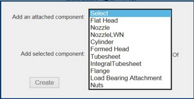
There are two ways to add a component:
(1) When no components have been added to an assessment, a pop-up window will appear, requiring the user to select a component.
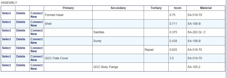
(2) Click 'Connect New' for an existing component on the assembly table - shown below.
Sample Component List in Assembly
Component Type
The component type, e.g. cylinder (shell), sphere (shell), nozzle, reinforcing pad, etc., is selected by the user on the 'add component' screen (shown below). This field can not be edited on the component input screen. If the wrong component type was selected, it should be deleted and the correct component added.
Component Name
Enter a user defined component name.
B16.5 or B16.47?
Select whether the flange is a standard design to ASME B16.5 or B16.47.
Flange Thickness
Enter the nominal thickness of the flange (flat thickness).
Nominal Thickness
Enter the original component thickness in requested units.
Components made from pipe: The ASME Code requires that the nominal thickness for components made from pipe be the specified thickness minus the mill undertolerance. Also, the Code requires that the nominal thickness for formed heads be the minimum specified thickness after forming. It is conservative to enter in the nominal thickness, assuming it is considered to be fully stressed, if the undertolerance or min specified thicknesses are not available.
Flathead Components (other than flanges and LWN nozzles): Enter the nominal thickness of the flat component. Note that the thickness of the flange at the weld is taken from the "Nominal thickness at flange" input.
Flanges and long weld neck nozzles: Input requirements are flange thickness (non 16.5 and 16.47 flanges) and nominal thickness at weld.
Different thickness at flange?
Select whether the nozzle has a different thickness at the flange-to-nozzle junction (Nozzles only).
Nominal thickness at flange
Enter the original thickness of the nozzle at the flange-to-nozzle junction in requested units. Note that for nozzle necks made from pipe, it is permissible to subtract the mill tolerance from the specified wall thickness.
The software uses this thickness as the governing thickness of the nozzle to flange weld.
Entered required thicknesses?
Select whether the required thickness is to be entered. This allows the software to use the thickness basis (Ref [1] Eqn 3.2) and apply the 'stress ratio' credit (Rts < 1) to the MAT at the rating pressure (MAWP or design pressure).
If the required thickness is not entered, the software uses the Pressure-Temperature Rating Basis (Eqn 3.4) for the MAT curve, where Rts = 1 at the entered rating pressure.
Required Thickness
The software allows the option of entering the pressure-based minimum required thickness for the component at the entered rating pressure on the Vessel page. If the minimum required thickness is available, it should be entered. The minimum thickness entered will used to compute the thickness basis stress ratio (Ref [1] Eqn 3.2). This ratio will be applied to determine the �stress ratio credit� reduction in the MAT.
The minimum required thickness should not include corrosion allowance.
Use Longitudinal Stress Basis?
For B31.3 piping systems, the user has the option of using the stress basis (Eqn 3.3) for the longitudinal stresses. The assessment of piping systems should consider the maximum stresses due to combined sustained and thermal loads.
Component Inner Diameter
Enter the component's inner diameter in the units indicated.
Allowable Stress
The allowable stress should correspond to the basic allowable stress for the condition under consideration.
Applied General Longitudinal Primary Stress
The input longitudinal stress for the combined (sustained and thermal) loads should include the combined stress due to pressure, dead loads, live loads and displacement strain for the condition under consideration, and for the sustained loads should include the stress due to pressure, dead loads and live loads.
The forces and moments in the piping system should be based on nominal dimensions. Stresses should be calculated based on nominal dimensions adjusted for metal loss, future corrosion allowances and mechanical allowances. Stress intensification should not be included.
The thermal stress calculation does not need to consider the full design range, but reflect the actual stress imposed at low temperature. Ref para 3.4.3.4.b [1].
Required thickness of Nozzle Neck at Nozzle to Shell Junction
If required thickness is entered and the component is a nozzle, the required thickness of the nozzle neck at the location of the nozzle to shell weld is entered.
Largest thickness of casting
Enter the largest thickness of casting (Castings only)
Governing thickness
For miscellaneous components, the user is required to enter the governing thickness. See [1] 3.4.2.1.e.
PWHT (and status has not been changed)?
Post Weld Heat Treated? If the component has been Post Weld Heat Treated, either during new construction or subsequently in the field, select "Yes". Otherwise, select "No".
Joint efficiency
Enter the weld joint efficiency that applies, this entry is available for cylindrical and spherical (shell) components.
Joint efficiency = 1 for all other components where thickness is not a function of joint efficiency.
Material of Construction
This cell contains a pull-down box for materials selection for the component.
Fine-grained practice?
Select whether the material has been made to fine-grained practice. "Y" should not be selected unless the user is certain of this.
Normalized?
Select whether the material has been normalized. Note that in the case where the SA specification requires that the material be normalized, this input does not appear as it is retrieved value from the software's materials database. "Y" should not be selected unless the user is sure.
Impact test was performed?
Select whether impact test was performed and the Charpy data is available.
If a Charpy impact test is required by the materials "SA" specification, and if a test temperature is given in the specification, then this input will not appear as it is a retrieved value from the software's material database.
Charpy test temperature
This field is for entry of the Charpy impact test temperature for the component. It must be verified that the Charpy tests meet ASME Code requirements. If a Charpy impact test is required by the materials "SA" specification, and if a test temperature is given in the specification, that temperature available in the software's material database and is looked up and reported on the Results page.
P1G1 or P2G2?
Select whether the the material is P1, Group 1 or 2. This input will not appear if the software's database contains this information.
Update
After entering or editing a component, click ![]() to store the data in the Assembly Table.
to store the data in the Assembly Table.
Assembly Table
This table documents the entered components, forming an assembly of vessel components which includes the connection configuration needed to compute the governing thickness and MAT for each component.
To edit a component in the table, click Select
To delete a component in the table, click Delete. Note that if a component has a dependent, i.e. a component welded to it and specified to be part of the component, the user will not be able to delete it until the dependent components are deleted.
For example, a head which has a nozzle and reinforcing pad welded to it cannot be deleted until the nozzle and repad are deleted.
To add components, click on Connect New. This will allow addition of a component. The component types which can be added will show as options on the "Add New Component" pop-up.