|
Inputs
|   |
|
Inputs
| |
Geometry and Construction Code
Select geometry based on the type and shape of the component.
Direction of Weld Seam
Select whether the seam direction is longitudinal or circumferential.
Internal Design Pressure, P
Enter the internal design pressure for the component. This input will appear only for pressurized components assessed to the API-579 code.
Design Fill Height, H
Enter the Design fill height (H) of the component. This input will appear only for atmospheric storage tanks assessed to the API-579 code.
Weld Joint Efficiency, E
Enter the weld joint efficiency of the weld being analyzed. The weld joint efficiency is typically indicated on the original construction code, if unknown use 0.7.
Thickness on Either Side of Weld
Select whether the wall thickness is the same or different on each side of the weld.
Nominal Thickness on First Side of Weld (Thinner), t1
Enter the original wall thickness for the thinner side of the weld.
Nominal Thickness on Second Side of Weld (Thicker), t2
Enter the original wall thickness for the thicker side of the weld.
Nominal Thickness, t
Enter the original component wall thickness in requested units.
Width of Plate, w
Enter the width of the plate, this input is only available for a geometry of flat plate.
Diameter on Either Side of the Weld
Select whether the diameter is the same or different on each side of the weld.
Nominal Inside Diameter on First Side of Weld. D1
Enter the original inside diameter for the first side of the weld.
Nominal Inside Diameter on Second Side of Weld. D2
Enter the original inside diameter for the second side of the weld.
Nominal Inside Diameter, D
Enter the original inside diameter of the component.
Location of Metal Loss
Select whether the metal loss is on the inside or outside of the component.
Uniform Metal Loss Remote from Damaged Region, LOSS
Enter the amount of uniform metal loss away from the local metal loss location at the time of the assessment.
Future Corrosion Allowance, FCA
Enter the future corrosion allowance value for the vessel per the construction code.
Allowable Remaining Strength Factor, RSFa
Enter the allowable remaining strength factor for the component. The recommended value for RSFa per API-579 Part 2 paragraph 2.4.2.2.d is 0.90. Refer to API-579 Annex 2F for guidance on establishing alternative values for RSFa.
Allowable Stress at Assessment Temperature, Sa
Enter the allowable stress of the material at the design temperature per the material specification.
Modulus of Elasticity at Assessment Temperature, Ey
Enter the modulus of elasticity of the material at the design temperature per the material specification.
Poisson’s Ratio at Assessment Temperature, v
Enter the Poisson’s Ratio for the material of vessel construction at assessment temperature, if unknown use a conservative value of 0.3.
Stress Classification for Determining Stress Factor, Hf
Select if the induced stresses are primary or secondary stresses.
Supplemental Loads
Check this box if there are supplemental loads to be included in the analysis.
Supplemental Thickness for Longitudinal Loads, tsl
Enter the additional thickness required to adjust for the supplemental loads.
Net Section Axial Force, F
Enter the net-section axial force, used only for flat plates and centerline offset of circumferential joints in cylinders.
Net Section Bending Moment, Mns
Enter the net-section bending moment, used only for flat plates and centerline offset of circumferential joints in cylinders.
B31 Piping Code Coefficient, Yb31
Enter value which can be found in [4] Table 304.1.1 for the case where t < D/6. Displays for ASME B31.3 Construction Code.
Mechanical Allowances, MA
Enter Values in requested units. Displays for ASME B31.3 Construction Code
Specific Gravity of Fluid, G
Enter value of specific gravity in requested units.
Type of Weld Misalignment
Select the appropriate type of weld misalignment for the assessment depending on axial or angular misalignment.
Centerline Offset at the Weld, e
Enter the offset of the centerline planes for each side at the weld joint.
Type of Peaking
Select if the peaking is Local or Global. Local means in a small area, while global means peaking is occurring on a significant portion of the weld seam.
Flat Plate End Attachments
Select if the Ends are Pinned or Fixed for the flat plate geometry. Pinned means able to rotate but cannot translate and Fixed means it cannot rotate or translate.
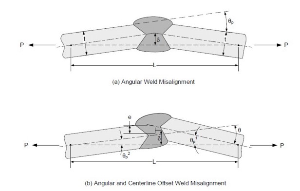
Height of Angular Peaking, ä
Enter the Height of angular peaking. See below graphic.
Characteristic Length of Angular Misalignment, L
Enter the characteristic length, the length of the base of a triangle along the line of force whose height equals the angular peaking. See below graphic.
Angle of Misalignment, čp
Enter the angle of angular misalignment. See below graphic.